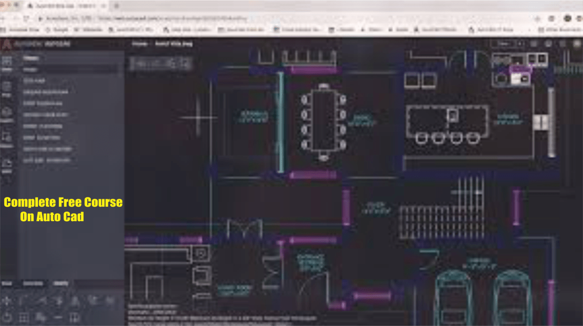
Before you start to use Auto cad modify commands, you need to know something about selecting object all of the modify commands require that you make one or more object selection. AutoCAD has a whole range of tools which are design to help you select just the object you need. This tutorial is designed to demonstrate the use of many of the selection option. As with so many aspect of AutoCAD, developing a good working knowledge of these option can drastically improve your drawing speed and efficiency.
Selecting object by picking
Perhaps the most obvious way to select an object in AutoCAD is simply to pick it. Those of you who have used other graphic based utilities will be familiar with this concept. Generally, all you have to do is place your cursor over an object click the mouse button and the object will be selected. In this respect
When you start a modify command such as ERASE, two things happen. First the cursor changes from the usual crosshairs to the pick box and second, you will see the “select object” prompt on the command line. Both of these cues are to let you know that auto cad is expecting you to select one or more objects
Select object
To select object, place the pick box over a part of the object and left-click the mouse. When the object has been pick it is heighted in a dashed line to how that is part of the current selection and the command line reports “1 found”. You will now see the “select object” prompt on the line again. At this point you can continue adding more object to the current selection by picking them.
When you pick one or more object in response to the “select object” prompt you are effectively creating a selection set. Selection sets are an important concept in Auto cad because they can be used to great effect, especially when drawing become large or complicated.
Selecting all objects
The all option is invoked by typing all at the “selecting object” prompt you can have used this option to select all the object in the object in the current drawing, no picking is required. Object on lucked or frozen layers are not selected by object on larger which are simple turned off are selected.
Using a previous selection
AutoCAD always remembers the last selection set you defined: this is very useful because you may need to make a number of change using different commands to the same group of object. In order to re-select the last selection set you can use the previous option. The previous option is invoked by tying P at the “select object” prompt.
Selecting the last object
You can select the last object created by entering L at the “select object” prompt
DRAWING OBJECT IN AUTOCAD
Introduction
These tutorial is design to show you how all of the auto cad draw commands work. If you just need information quickly, use the quick find toolbar below to go straight to the command you want or select a topic from the contents list above.

The drawing command can be used to create new object such as line and circles. Most AutoCAD drawings are composed purely and simply from these basic components. A good understanding of the draw commands is fundamental to the efficient use of AutoCAD.

In common with most auto cad commands, the draw command can be started in a number of ways command names or short – cut can be entered at the key board; command can be started from the draw pull-down menu, shown on the right or from the draw toolbar. The method to use is dependent upon the type of work you are doing and how experienced a user you are. Don’t worry too much about this just use whatever method feels easiest or most convenient at the time. Your drawing technique will improve over time experience so don’t expect to be working very quickly at first.
If you are working with the pull-down menus, it is worth considering the visual syntax that is common to all pull-down used in the window operation system. For example, small arrows, next to a menu item means that the item leads to a sub-menu that may contain other commands or command option. An ellipsis, “…” after a menu item means that the item displays a dialogue box. These little visual clues will help you to work more effectively with menu because they tell you what to expect and help to avoid surprise for the new corner.
Lines
Lines are probably the simplest of auto cad object. Using the line command, a line can be drawn between any two points picked within the drawing area. Lines are usually the first object you will want to draw when start a new drawing because they can be used as “construction lines” upon which the rest of your drawing will be based. Never forget that creating drawing with AutoCAD is not so dissimilar from creating on a drawing board. Many of the basic drawing method are the same.
Anyone familiar with mathematics will know that line drawn between points are often called vectors. This terminology is used to describe the type of drawing that auto cad create. AutoCAD drawing are generically referred to as “vector” drawing are extremely useful where precision is the most important criterion between they retain their accuracy. Irrespective of scale.
The line command
Toolbar Draw
Pull-down draw line
Keyboard line shortcut L s

With the line command you can draw a simple line from one point to another. When you pick the first point and move the cross-hairs to the location of the second point you will see a rubber band line which shows you where the line will be drawn when the second point is picked. Line object have two ends (the first point and the last point). To can continue picking point and auto cad will draw a straight line between each picked point and the previous point. Each line segment drawn is a separate object and can be moved or crossed as required. To end this command just hit the +key on the keyboard.

Command Sequence
Command: LINE
Specify first point: (pick p1)
Specify next point or undo: (pick p2)
Specify next point or undo: (to end)
You can also draw line by entering the co-ordinates of their and point at the command prompt rather than picking their position from the screen. This enable you to draw lines that are off screen, should you want to. You can also draw lines using something called direct distance entry.
THE CONSTRUCTION LINE COMMAND
Toolbar Draw
Pull-down construction line keyboard X LINE short-cut
XL
The construction line command creates a line of infinite length which passes through two picked points construction lines are very useful for creating construction framework or girds within which to design.
Construction line are not normally used as object in finished drawing, it is usual, therefore to draw all your construction lines on a separate layer which will be turned off or frozen prior to printing. Because of their nature, the zoom extents command option ignores construction lines.
Command sequence
Command: X LINE
Specify through point: (pick a second point)
Specify through points: (to end or pick another point)
You may notice that there are a number of option with that command. For example the “Hot” and “ver” option can be used to draw construction line that are truly horizontal or vertical. In both these case only a single pick point is required because the direction of the line is predetermined. To use a command option, simple enter the capitalized part of the option name to the command prompt. Follow the command sequence below to see how you would draw a construction line using the horizontal option.
Command sequence
Command: X LINE
Hor/ver/ang/bisect/offset/<from point>: H
Through point: (pick a point to position the line)
Through point: (to end or pick a point for anther horizontal line)
The Ray Command
Toolbar custom
Pulldown draw
Keyboard RAY
The ray command creates a line similar to a construction line extends infinitely in only one direction from the first pick point. The direction of the ray is determined by the position of the second pick point
Command sequence
command: RAY
specify start points: (pick the start point)
specify through point: (pick a second point to determine direction)
specify through point: (to end or pock another point)
THE FUNCTION KEY
Many of the modes described above can be controlled quickly using the keyboard function keys. In most case this is quicker than using a pull-down or the command line. The function keys are arranged along the top of your keyboard. AutoCAD uses function keys F1 to F11. Their use is described below.
The F1 key on your keyboard bring up the “AutoCAD help: user Documentation” dialogue box. You can use this dialogue box to search for help on any AutoCAD command or topic. To find help on a command topic, click on the index lab and enter a keyboard. You will usually be given a list of option in the topic list; select the most appropriate and click the “display” button to see the item.

The F2 key is used to toggle (turn on and off) the AutoCAD text window. This is a floating version of the command window which can be resized to suit your requirement. The text window contains the whole command history from the beginning of the drawing session. If you wish, you can scroll, back to see which command you have used. The text window is also useful for viewing the result of command like LIST which report to the command line on a number of line which may scroll off the command window and make them to view.

The F3 toggles running object snaps on and off.
The F4 key on your keyboard toggle table mode on and off. This only has an effect if a digitizing table has been calibrated.

The F5 key cycles through the isoplanes, this only has an effect if “isometric snap/grid” mode is on. The option is left, top and right. The different options describe the plane in which Orth mode works. It also affects the orientation of isocircles drawn will the ellipse command. The illustration on using the corresponding isoplane.
The F6 key is a three-way toggle which changes the co-ordinate reading in the status bar. By default, the status bar shows co-ordinates using the Cartesian system, you can use the F6 key to turn the co-ordinate readout off and to change to the polar system when you are in pick mode.
The F7 key is used to toggle grid mode on and off. When grid mode is on a grid of dots is shown on the screen as a drawing aid. You can set the grid spacing by using “Drafting Setting” from the “Tools” pull-down. The grid points do ton necessarily reflect the snap setting they can be set independently, and however, you can force the grid to reflect the snap setting by giving the grid setting a value of zero.
The F8 key on your keyboard can be used to toggle Orth (orthogonal) mode on and off when Orth mode is on AutoCAD will only allow you to draw either vertical or horizontal lines. You can think of it as bring a computer version of the parallel motion on your drawing board. You can see if Orth mode is on by looking at the status bar. The “ORTHO” button is shown “pushed in” when Orth is turned on.
The F9 key can be used to toggle snap mode on and off snap makes the crosshair jump t point on a defined grid. The snap spacing can be set using the “drafting setting” dialogue box from the “Tools” pull-down menu. You can also see if snap mode is on by looking at the status bar.
The F10 key is used to switch polar tracking off and on polar Tracking allows you to snap to specific angles and these are use definable.
The F11 key toggle object snap tracking on and off.
hope these article help if yes you can leave comment below.



 free course online